ASG150 Test Signal Generator
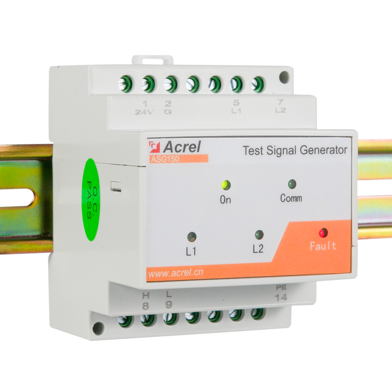
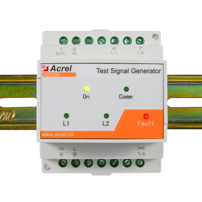
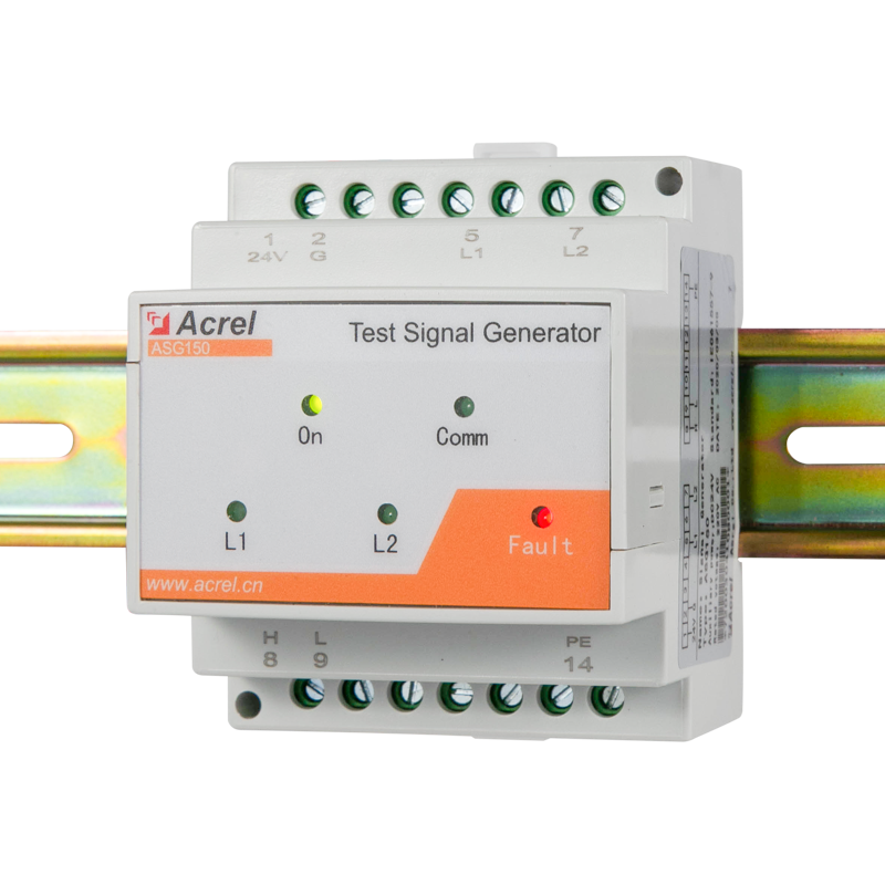

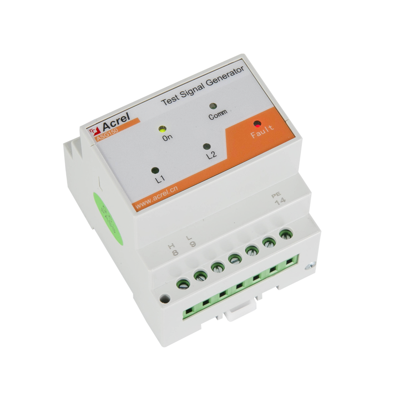
ASG150 Test Signal Generator
● Generating Fault Location Signal
● Detection of L1 and L2 disconnection
● LED indicators: On, Comm, Test
● CAN bus
● Auxiliary power supply: DC24V
-
 ASG150.pdf


Dimension

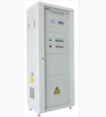
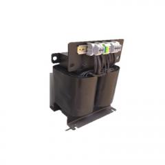
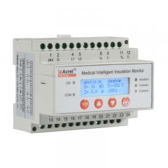
Application

LED indicator instructions
|
Indicator light |
Instructions |
|
On |
When the device is in normal operation, the indicator flashes, and the flickering frequency is about once a second |
|
Comm |
Indicate the status of device communication, when there is data transmission, the indicator flashes. |
|
Test |
When the indicator light is green, it indicates normal operation of the system; When red, it indicates the instrument has L1, L2 disconnection fault; When the red and green flash alternately, it indicates the device is generating fault location signals. |
Common problems
Make sure the connection is correct before the system is powered on. For common problems, according to the fault phenomena in the table below, targeted investigation can be carried out.
|
No. |
Fault phenomenon |
Possible causes and troubleshooting |
|
1 |
The device is not lit. |
The 24V power supply is not connected properly. Check the connection of terminals 8 and 9 and make sure it is correct. |
|
2 |
Test indicator is red. |
Terminals 3 and 5 are not reliably connected to the secondary side of the isolation transformer. Check and make sure that the connection is correct until the light turns green after power on. |
Note: All the above faults should be checked by power off, and the wiring should be adjusted until everything is normal.
text text
text text
text text
|
Auxiliary power supply |
Voltage |
DC24V(±25%) |
|
Power consumption |
≤2VA |
|
|
Monitored system |
Rated voltage |
0~242V AC |
|
Rated frequency |
45-60Hz |
|
|
Locating current |
<1mA |
|
|
Communication |
Interface |
CAN bus |